The RCP Travelling Block Monitor (TBM) is an electronic crown and drillfloor saver system for offshore and land drilling rigs. The system continuously monitors travelling block height and speed, applies intelligent adaptive braking curves to calculate a safe working envelope, and automatically actuates the auxiliary brake — and main brake if required — to prevent crown and drillfloor collisions. System action time is under 0.5 seconds. Block height and speed are measured to ±0.1ft and ±0.1ft/s respectively.
RCP TBM systems are highly customisable and fully specified through a Functional Design Specification (FDS) agreed with the customer prior to supply.
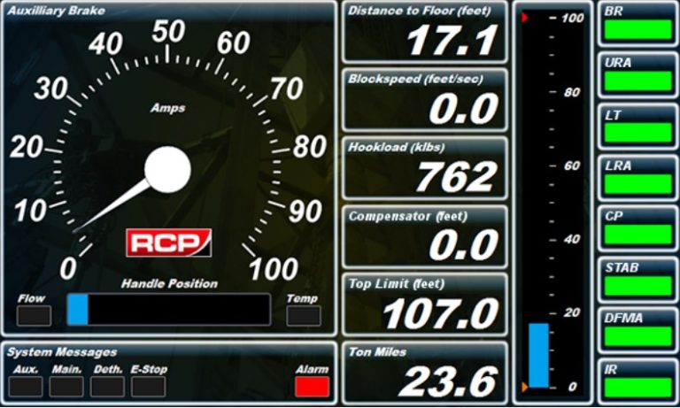
TBM – Drillers HMI Main Screen
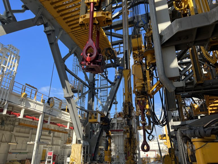
Dual Derrick Travelling Blocks with Top Drives
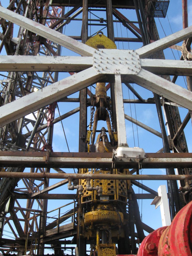
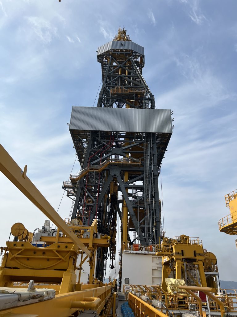
Derrick, with a Travelling Block and a Top Drive
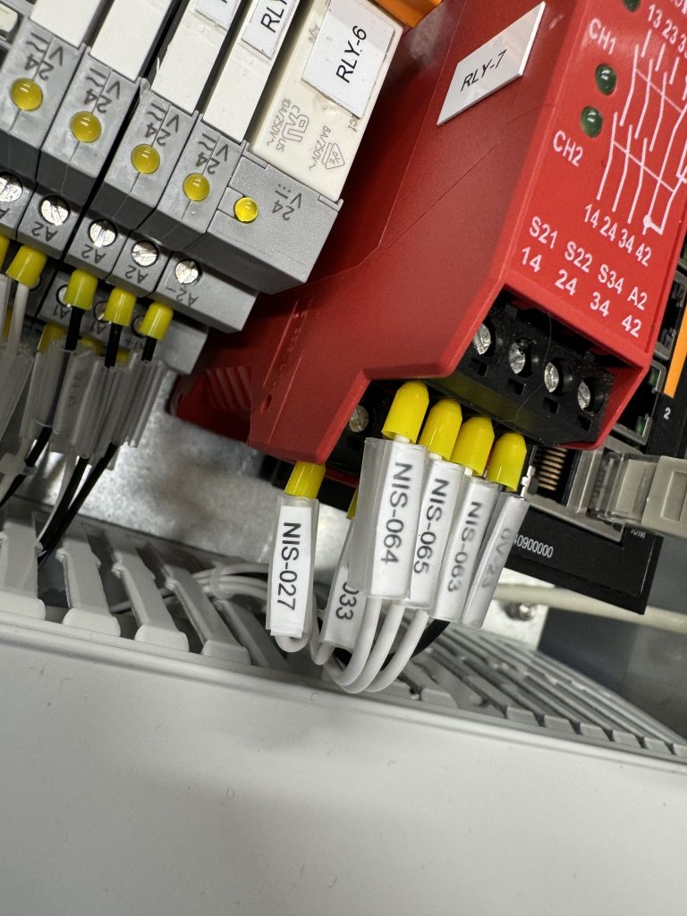
TBM – E-Stop Relay
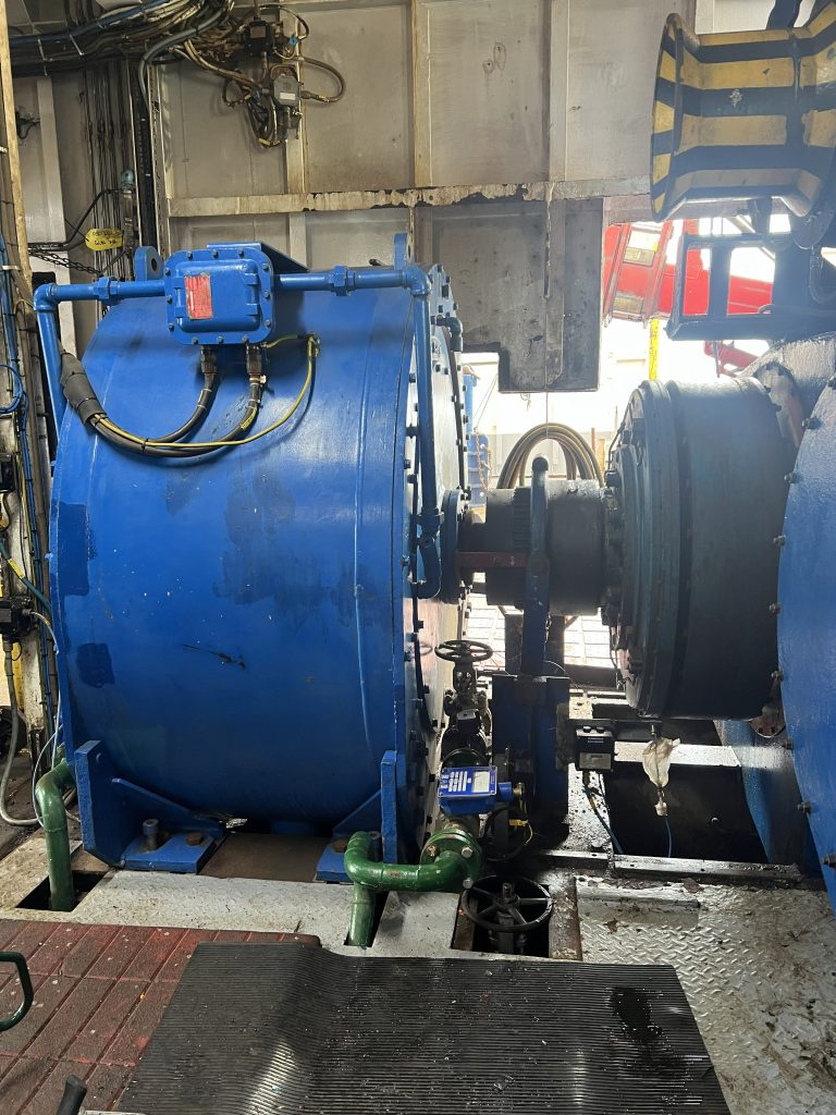
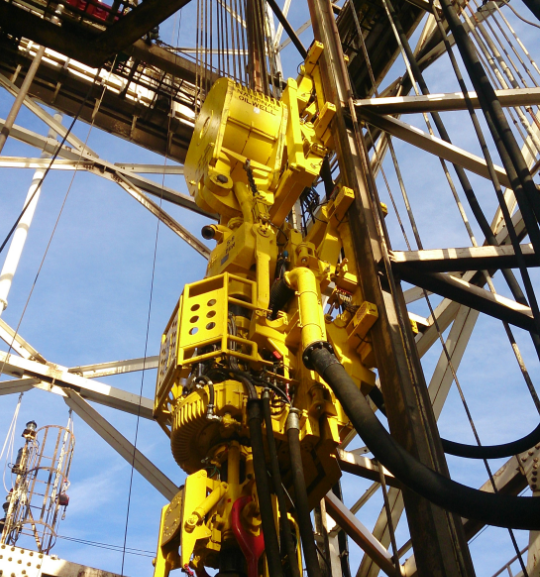
Elmagco Brake on the Drawworks
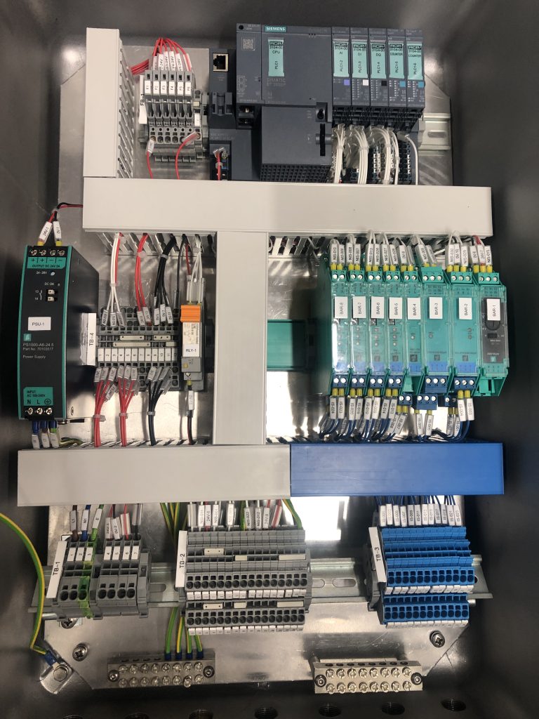
TBM – Zone 1 Controller Backplate
Dual Derrick Drilling Package
Travelling Block with a Top Drive
Monitoring & Control
The TBM controller monitors block height, block speed, and hookload in real time. The PLC computational cycle is under 30ms, with system action time under 0.5 seconds from detection to brake actuation. When the travelling block exceeds the predefined safe working envelope, the system initiates the auxiliary brake. If auxiliary braking is insufficient, main brake actuation follows automatically. Additional interlocks are available on request.
Adaptive braking curves are applied to minimise wear and tear on rig equipment and reduce disruption to drilling operations. Braking parameter autocalibration is included as standard.
The system is compatible with band brake, disc brake, electromagnetic brake, water-based brake, and oil shear-based brake systems, and can be designed for compatibility with DC/SCR, AC, hydraulic, mast, and ram drilling rigs.
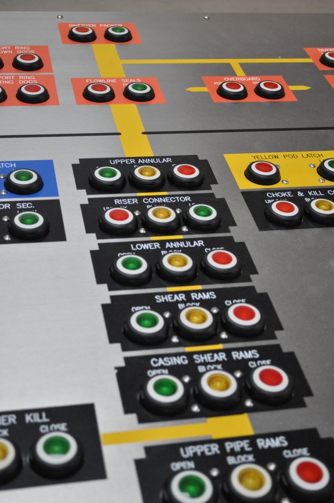
Drillfloor Anti-Collision (ACS) — Optional
The TBM can be expanded to provide Top Drive Anti-Collision and Elevator Anti-Collision capability, monitoring drill floor equipment positions to prevent collisions between the travelling block and iron roughneck, link tilt, pipe racking arms, and other drill floor equipment. Optional proximity sensors (0–10mm or 0–30mm sensing distance) and inclination sensors (0–180°) support collision zone management. Wireless proximity and angle sensing solutions are also available.
HMI & Driller Interface
The system is supplied with a 7-inch colour touchscreen HMI (Ex e rated). The HMI displays auxiliary brake current, block height, block speed, hookload, block position, upper and lower limits, ton mile calculation (resettable), alarms, and system configuration information. Units are user-selectable between imperial and metric. A guided reset procedure and full system maintenance and setup are accessible directly from the driller’s HMI. Driller controls include Accept, Override, Reset, and Emergency Stop.
Data Logging & Remote Access — Optional
Optional data logging provides six months of FIFO event storage, expandable to a customer-specified timeframe. Remote access is available as an extension to the data logging system. Third-party data handover is supported over Profinet, Profibus, TCP/IP, Modbus, and Serial protocols.
Technical Specifications
Hazardous Area Classification
All TBM field devices are rated to at least ATEX Zone 2, −20°C to +50°C, IP65. Four certification options are available:
- Option 1 — TBM field devices certified for ATEX Zone 2
- Option 2 — TBM field devices certified for ATEX Zone 1
- Option 3 — Full TBM system certified for ATEX Zone 2
- Option 4 — Full TBM system certified for ATEX Zone 1
Standards Compliance
Systems are designed to IEC/EN 60079-0, IEC/EN 60079-7, IEC/EN 60079-11, IEC/EN 60079-28, and BS 6761. The system is recommended for use by API RP54 and can further comply with API RP551, IEC 61439, IEC 60204-1, IEC 61508, EN 55022, EN 55024, IEC 60950-1, and API 554.
Further Expansion
The TBM architecture supports expansion to include WOB and ROP parameter display, wind sensor integration, drill bit protection, derrick loading and protection, collision zone management, and emergency shutdown integration.
Frequently Asked Questions about Travellng Block Monitor
Q: What is a Travelling Block Monitor (TBM)?
a. Travelling Block Monitor (TBM) is an Electronic Crown and Floor saver system. TBM continually monitors the travelling block movement, determines the direction, speed and height. This is an automatic system; therefore, if hazardous collision conditions with the floor or crown are detected, the TBM automatically enables the auxiliary brake, and if required, the TBM will slow down the Drawworks motors and/or enable the main rig brake.
Q: Is using the TBM a standard practice?
a. API Recommended Practice 54, states that Drawworks should be equipped with a safety device that prevents the travelling block from striking the crown block. The RCP TBM is an electronic crown saver ensuring that the block cannot strike the crown.
b. Commonly, drilling rigs are equipped with a pneumatic crown saver (crown-o-matic). It is recommended to utilise the TBM as a redundant safety system, where the TBM would act to stop the blocks before the pneumatic crown saver. In the event of the pneumatic crown saver or main brake failing, the TBM would ensure that the auxiliary brake is actuated and that the upwards throttle is removed, thus minimising the chance of a travelling block-crown collision.
Q: Is the automatic TBM action safe for drilling hoisting equipment?
a. The TBM utilises intelligent braking profiles, which ensure that braking operation does not damage the equipment.
b. When travelling downwards, the TBM integrates the drillers’ input, hookload, distance to the floor and block speed values. This calculation allows the TBM to tailor an intelligent braking profile for each specific operational condition and enable the brakes at the right time, avoiding collisions with smooth braking action and avoiding excessive operational disruptions.
c. When travelling upwards, the TBM integrates the drillers’ input, hookload, distance to the floor and block speed values. This calculation allows the TBM to tailor an intelligent braking profile for each specific operational condition. When determined as needed, the TBM will cut the drawworks throttle and pulse the auxiliary brake, ensuring that the block inertia does not damage the drill line (avoiding birdnesting).
Q: Can the TBM be tailored for a specific piece of equipment or operational requirement?
a. Each TBM crown and floor saver system can be tailored to work with different drilling equipment. This includes different drawworks and drawworks prime movers, different types of auxiliary brakes and different types of main brakes.
b. The TBM can be further extended to provide an Anti-Collision System to avoid block collisions with other drilling equipment.
c. The TBM can be further extended to provide a Drill Bit Protection System to limit the Rate of Penetration and Weight on Bit, increasing the drill bit longevity.
d. The TBM is suitable for operation on onshore (Land Drilling) and offshore drilling (Fixed Platform, Semi-Submersible, Jack-up, Drilling Ship, Tender Barge) rigs.
Q: Is TBM available in a fail-safe and a non-fail-safe configuration?
a. The RCP travelling block monitor can be set up for a fail-safe or a non-fail-safe operation. Meaning that the TBM can become the main crown and floor saving system, not allowing operations to take place unless the system is operational. Or TBM can be a secondary system, where, if required, the crown and floor saving functions are overridden.
b. By default, TBM operates as a redundanct system for the auxiliary brake. If TBM does not observe the required braking force from the auxiliary brake, it will enable the main brake, ensuring that a collision is avoided even if the auxiliary brake has failed.
TBM Product Information Summary
Download TBM product information summary here